¶ Alerts and Notifications
E-Drive provides varying notifications and alerts to indicate current and historical system status.
Alerts vary in severity, from indication of minor issues that may not impact operation of the E-Drive system, through to indication of critical errors that prohibit system operation. Critical alerts are shown on-screen and are generally accessible as follows:
- Press the alert triangle located at the top of the E-Drive screen
- Press the flashing PAUSED icon when visible (for power inhibit notifications)
- Choosing the Alert page which is available on the nav station touchscreen screen menu.
Issues vary from GREEN (low severity) through to RED (high severity). If multiple alerts are present, the alert icon at the top of the screen changes colour to indicate the highest severity present.
¶ On-Screen Alert Notifications
On-screen notifications appear as shown in the following example; each notification is described in the ensuing table. These notifications can be dismissed, but will re-appear after 5 seconds until the condition has been resolved.
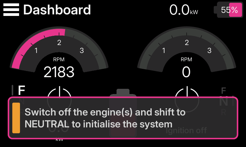
| On-screen Notification | Action(s) Required |
|---|---|
| System initialising...DO NOT START ENGINE | The system requires a short time to initialise after the ignition is switched on. Wait for this prompt to disappear before starting the engine! |
| Stop the engine and shift to neutral to initialise the system |
|
| Switch off the ignition and switch on again to initialise the system |
|
| Drive mode is paused. Tap for more info. | Press the notification to learn why Drive Mode is paused. |
| Select neutral to enable throttle | Move the throttle into the neutral position |
| The E-Drive motor does not operate in neutral | Deselect the throttle neutral switch, then move the throttle into gear. |
| An update is being applied, please wait ... | Wait for this dialog to disappear BEFORE starting the engine |
The following notifications may also appear when appropriate; the notification persists for five seconds.
| On-screen Notification | Action(s) Required |
|---|---|
| System will exit drive mode shortly | None. |
| System automatically switched to Standby due to inactivity | None. |
¶ Power Inhibit Notifications
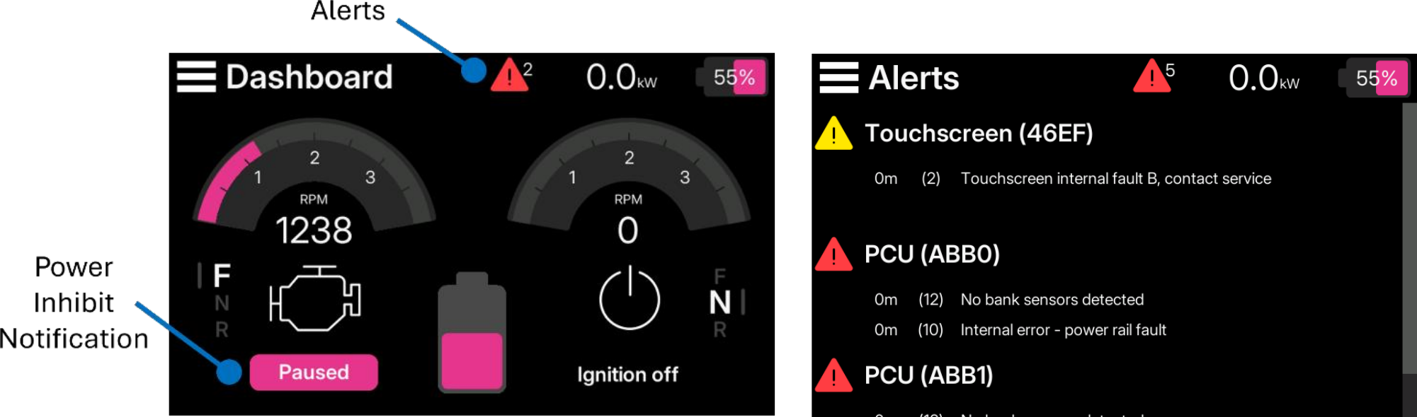
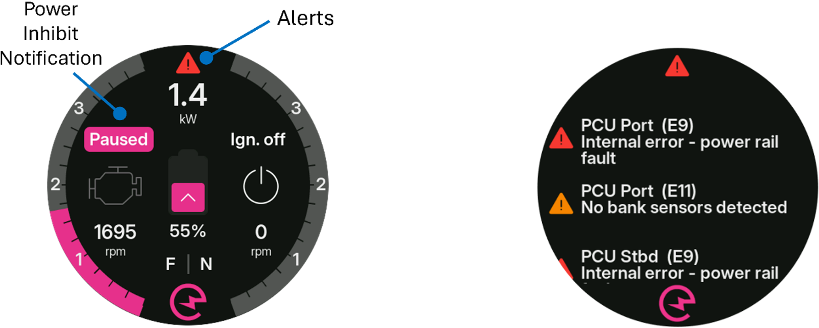
If a condition prohibits generation or drive, a flashing Paused button is shown on the E-Drive screen to indicate E-Drive operation is inhibited. The following table provides a list of all conditions that can cause a power inhibit notification.
| Power Inhibit Notification | Description |
|---|---|
| Batteries Offline | All detected battery sensors report battery contactors are open resulting in a battery capacity of zero. |
| BMS (IO) | The system detected a stop charge/discharge signal from the physical inputs to the PCU. |
| BMS Stop Charge | The BMS indicates battery charging is currently prohibited. |
| BMS Stop Discharge | The BMS indicates battery discharging is currently prohibited. |
| Data Missing | Information necessary for safe operation of the system is unavailable or out of specification; review the Alerts screen for additional information. |
| Diagnostic Mode Active | Operation is limited because the system is in diagnostic mode. |
| Engine Warming Up | The engine temperature is below the configured by user settings. |
| Ignition OFF | The engine ignition (for the specified hull) needs to be powered on for the system to operate. |
| Manoeuver | Throttle changes indicate manoeuvring is in progress (only applicable when generating). |
| Motor Disabled | The motor controller is not able to function correctly; review the Alerts screen for additional information. |
| RPM High | The engine RPM is too high for the system to operate. In some systems, the E-Drive motor may be unable to generate useful power over the entire engine RPM range. |
| RPM Low | The engine RPM is too low for the system to generate power. This notification shows if the engine is not running, or if the engine RPM is below the minimum allowed RPM to generate power (which may be above the engine idle speed). |
| SoC Above Threshold | The battery state of charge is above the configured maximum charge limit (see the Controls screen; only applicable when generating) |
| SoC Below Threshold | The battery state of charge is below the configured minimum discharge limit (see the Controls screen; only applicable when driving). |
| System Error | One or more alerts prevent system operation; review the Alerts screen for additional information. |
| Temp. too High | One or more temperature sensors indicate the system is operating above a safe operating temperature limit. |
| Temp. too Low | One or more temperature sensors indicate the system is operating below a safe operating temperature limit. |
| Voltage too High | The voltage measured by the motor controller is above the maximum allowed threshold. |
| Voltage too Low | The voltage measured by the motor controller is below the minimum allowed threshold. |
¶ Alerts
A full list of alerts is provided in the following table. Alert severity is characterised according to level, with alert level 5 the most critical and alert level 1 the least critical.
¶ Bank Sensor Alerts
| ID | Alert | Level | Cause | Actions/Notes |
|---|---|---|---|---|
| 1 | Configuration integrity error | 4 | Corrupted settings | The system runs with factory defaults |
| 2 | Startup self-check failed | 4 | Hardware fault on PCB or software glitch | |
| 3 | Internal software error | 4 | A software guardrail outside of normal operating limits was breached | Affected module(s) stops operating, the system may or may not continue operating |
| 4 | Temperature too high to charge | 4 | The temperature is higher than the maximum charge setting | Bank sensor reports bank not allowed to charge |
| 5 | Temperature too high to discharge | 3 | The temperature is higher than the maximum discharge setting | Bank sensor reports bank not allowed to discharge |
| 6 | Temperature too low to charge | 4 | The temperature is lower than the minimum charge setting | Bank sensor reports bank not allowed to charge |
| 7 | Temperature too low to discharge | 3 | The temperature is lower than the minimum discharge setting | Bank sensor reports bank not allowed to discharge |
| 8 | Voltage too high | 4 | The voltage is higher than the maximum setting | Bank sensor reports bank not allowed to charge |
| 9 | Voltage low - charge batteries | 2 | The voltage is lower than the warning setting | None, alert only |
| 10 | Voltage too low - charge immediately | 3 | The voltage is lower than the minimum setting | Bank sensor reports bank not allowed to discharge |
| 11 | Battery voltage imbalance | 3 | The difference in voltage between blocks of the string exceeds the configured allowable maximum | None, alert only |
| 12 | CAN error – Integrel network | 1 | Bus errors on the CAN physical layer | None, alert only |
| 13 | Temperature sensor fault | 3 | Sensor is disconnected or faulty (short circuit to high/low) | Temperature limits/warnings/protections are disabled |
| 14 | Missing voltage tap | 3 | Voltage taps are backwards or wrongly configured | Bank sensor cannot report data, bank appears offline |
| 15 | Internal error - power rail fault | 4 | One or more internal supply rails are faulty (PCB) | |
| 16 | Voltage measurement fault | 4 | Voltage reading is outside the coherence limits | Bank sensor cannot report data, bank appears offline |
| 17 | Battery contactor is open | 2 | The contactor IO input indicates the contactor is open | Bank sensor reports battery is offline |
| 18 | System service required when possible | 2 | Reset protection triggered | Alert persists until the data is cleared |
| 19 | Imbalance between battery banks | 2 | This bank sensor detects significantly different current to the others |
¶ PCU Alerts
| ID | Alert | Level | Cause | Actions/Notes |
|---|---|---|---|---|
| 1 | Configuration integrity error | 4 | Corrupted settings | The system runs with factory defaults |
| 2 | Startup self-check failed | 4 | Hardware fault on PCB or software glitch | |
| 3 | Internal software error | 4 | A software guardrail outside of normal operating limits was breached | Affected module(s) stops operating, the system may or may not continue operating |
| 4 | System voltage too high | 4 | Voltage on the EM 48V terminals or reported by the BMS exceeds the maximum voltage setting | |
| 5 | System voltage too low | 3 | Voltage on the EM 48V terminals or reported by the BMS is lower than the minimum voltage setting | |
| 6 | Output current too high | 4 | The EM output current is higher than the maximum setting | |
| 7 | EM measured RPM invalid | 4 | Invalid RPM (negative) reported by the motor controller | The motor is disabled until the system is power cycled |
| 8 | RPM divergence engine/EM detected | 2 | Difference between Controller and engine RPM readings | None, alert only |
| 10 | Internal error - power rail fault | 4 | One or more internal supply rails are faulty (PCB) | None, alert only |
| 12 | No bank sensors detected | 3 | No bank sensor devices found on the Integrel network | System runs with BMS data only, or in fallback mode |
| 13 | BMS contactor open | 2 | The BMS reports a contactor is open, or is about to open | The system stops charging/discharging accordingly |
| 14 | BMS communication unavailable | 2 | No BMS is detected on the N2K network, or there is a conflict or other N2K issue | System runs with bank sensor data only, or in fallback mode |
| 15 | N2K BMS configuration incorrect | 2 | Multiple BMS devices matching the configured battery system type were found, or the Mastervolt battery count in the configuration does not match the number of batteries configured in the gateway | System runs with bank sensor data only, or in fallback mode |
| 16 | N2K protocol error | 2 | Too many devices on the network, or another devices is conflicting with the source address | System runs with bank sensor data only, or in fallback mode |
| 19 | Supply voltage too low | 2 | The supply voltage to the system (12V) is below 9V | None, alert only |
| 20 | CAN error - Integrel network | 2 | Bus errors on the CAN physical layer | |
| 21 | CAN error - Engine | 2 | Bus errors on the CAN physical layer | |
| 22 | CAN error - N2K | 2 | Bus errors on the CAN physical layer | |
| 23 | CAN error - Throttle | 2 | Bus errors on the CAN physical layer | |
| 24 | Engine temperature too high | 4 | The engine temperature is higher than the maximum setting | None, alert only |
| 25 | Engine temperature sensor fault | 3 | Sensor is disconnected or faulty (short circuit to high/low) | None, alert only |
| 26 | Ambient temperature too high | 2 | The ambient temperature is higher than the maximum setting | None, alert only |
| 27 | Ambient temperature sensor fault | 3 | Sensor is disconnected or faulty (short circuit to high/low) | None, alert only |
| 28 | EM temperature too high | 4 | One or more of the phase/bearing temperatures is higher than the maximum setting | The motor is disabled until it cools down |
| 29 | Motor phase temperature sensor fault | 2 | Sensor is disconnected or faulty (short circuit to high/low) | Alert only, unless all are faulty, in which case the system runs in fallback temperature mode |
| 30 | Bearing temperature sensor fault | 2 | Sensor is disconnected or faulty (short circuit to high/low) | Alert only, unless all are faulty, in which case the system runs in fallback temperature mode |
| 31 | Throttle communication issue, engine side | 3 | Unexpected/inconsistent signal values on digital throttle network | System does not operate, and the bypass relay is opened to return control to the digital throttle system directly |
| 32 | No communication with throttle system | 2 | No data received on the throttle CAN network | System does not operate, and the bypass relay is opened to return control to the digital throttle system directly |
| 33 | Throttle signal incoherent, check cables | 3 | Analog throttle signal is mismatched or faulty | System does not operate, and the bypass relay is opened to return control to the analog throttle directly |
| 34 | Throttle control hardware fault | 3 | Faulty analog throttle ADC or DAC | System does not operate, and the bypass relay is opened to return control to the analog throttle directly |
| 35 | Controller temperature too high | 4 | PCU temperature (PCB) | None, alert only |
| 36 | Motor controller temperature too high | 3 | EM Controller | The motor controller will stop operating until it cools down |
| 37 | PCU temperature sensor fault | 3 | Hardware fault on PCB – PCU | None, alert only |
| 38 | Motor controller communication error | 4 | Error on EM_CAN / unexpected loss of data | The motor is disabled until the issue clears |
| 39 | Motor controller direct fault | 4 | Fault reported by EM controller directly | The motor controller acts according to the fault |
| 40 | Internal hardware fault | 4 | reserved | |
| 41 | Throttle bypass relay opened | 4 | The throttle bypass relay is opened (not shown until it has closed once after power on) | None, alert only |
| 42 | CAN error - Motor | 4 | Bus errors on the CAN physical layer | |
| 43 | Motor controller initialisation failed | 4 | Error from the motor controller during initialisation | The motor is disabled until the system is power cycled |
| 44 | Throttle control cannot communicate with engine | 4 | No throttle data received on the engine CAN network | System does not operate, and the bypass relay is opened to return control to the digital throttle system directly |
| 45 | Phase short - system disabled, contact service | 4 | The EM phase short detection triggered | |
| 46 | EM power overload, reduce throttle | 4 | The EM power exceeded the allowed demand | None, alert only |
| 47 | Temperature derate mode is active due to faulty sensors | 3 | All bearing or all phase temps are broken | The system runs in fallback temperature mode |
| 48 | Gearbox actuator error - E-Drive is not available | 4 | missing or "not-ready" from gear actuator | The system does not operate |
| 49 | Engine is overloaded, reduce E-Drive charge power | 2 | Engine reports 100% load for 8 seconds or more | After 20 seconds, the system switches to standby mode |
| 50 | System service required when possible | 2 | Reset protection triggered | Alert persists until the data is cleared |
| 51 | Throttle supply voltage too low | 2 | One or both throttle input voltages is below 2.5v | None directly, other throttle safety logic may apply |
| 52 | Gearbox position sensor fault | 2 | Forward/reverse inputs are not in a valid state | If sensors conflict, assume NEUTRAL. If one is faulty, use the other as in/out gear |
| 53 | Motor controller data mismatch, motor disabled | 4 | Invalid operating condition for the motor controller (inconsistent data) | Motor controller operation is disabled until the PCU is power cycled |
| 54 | Check isolation fuse | 3 | The motor controller reports a fault with the isolation fuse | The system runs in fallback (reduced) power mode |
| 55 | Motor phase short, contact support | 4 | The motor controller reports a phase in the motor has shorted | The system does not operate |
| 56 | Large current divergence between BMS and Bank Sensor data | 3 | N2K BMS current and bank sensor current significantly different for an extended period | The system runs in fallback (reduced) power mode |
| 57 | EM coolant temperature sensor fault | 1 | None, alert only | |
| 58 | EM coolant temperature too high | 1 | None, alert only | |
| 59 | Throttle interface unavailable - use engine | 4 | Processor communication failure | The system will not operate |
| 60 | Throttle interface invalid data - use engine | 4 | Processor communication failure | The system will not operate |
| 61 | Coprocessor communication error | 4 | Processor communication failure | The system will not operate |
| 62 | BMS behaviour suggests balancing required | 1 | Rapid cycling of ATC | Alert only |
| 63 | Unexpected EM keyswitch state | 4 | Messages on EM CAN bus with ignition off | Alert only |
¶ Touchscreen Alerts
| ID | Alert | Level | Cause | Actions/Notes |
|---|---|---|---|---|
| 1 | Touchscreen internal fault A, contact service | 2 | A software error has occurred, Contact Support | None, alert only |
| 2 | Touchscreen internal fault B, contact service | 2 | A software error has occurred, Contact Support | None, alert only |
| 3 | Touchscreen temperature too high | 2 | The onboard temperature exceeds 80C | None, alert only |
| 4 | Integrel CAN data network fault, check cables | 2 | Bus errors on the CAN physical layer | |
| 5 | Touchscreen supply voltage too low | 2 | ||
| 6 | Touchscreen internal fault C, contact service | 2 | A software error has occurred, Contact Support | |
| 7 | System fault in device, contact service | 3 | A device connected to the Integrel network is in failsafe mode | |
| 8 | Incompatible device detected, please update immediately | 3 | A device with a different Integrel protocol revision is connected | |
| 9 | Battery charge is low, start engine and switch to Generate mode! | 3 | ||
| 10 | Battery charge very low, Drive will be disabled soon | 3 | ||
| 11 | 2 | |||
| 12 | CAN initialisation failed, contact service | 2 | ||
| 13 | CAN transmission error, check cables | 2 | ||
| 14 | CAN reception error, check cables | 2 | ||
| 15 | CAN communication interrupted, check cables | 2 | ||
| 16 | Check configuration, cannot match system to hull | 2 | Multiple PCU reporting the same hull ID | |
| 17 | A device disconnected from the Integrel network | 3 | None alert specific, but other devices on the network may handle the loss of the device depending on what it is |
How E-Drive Works ⟵ | User Guide Contents | ⟶ Support and Maintenance