¶ Controller LED Status
Three LEDs on the Controller indicate operational states, warnings, or error conditions.
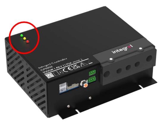
| LED State | Indication |
|---|---|
| 🟢 Green solid | Master Controller |
| 🟢 Green flash | Slave Controller |
| 🟠 Orange solid | A warning is active |
| 🟠 Orange flash | More than one warning is active |
| 🔴 Red solid | An error has occurred |
| 🔴 Red flash | More than one error has occurred |
¶ Advanced Diagnostics (P-Codes)
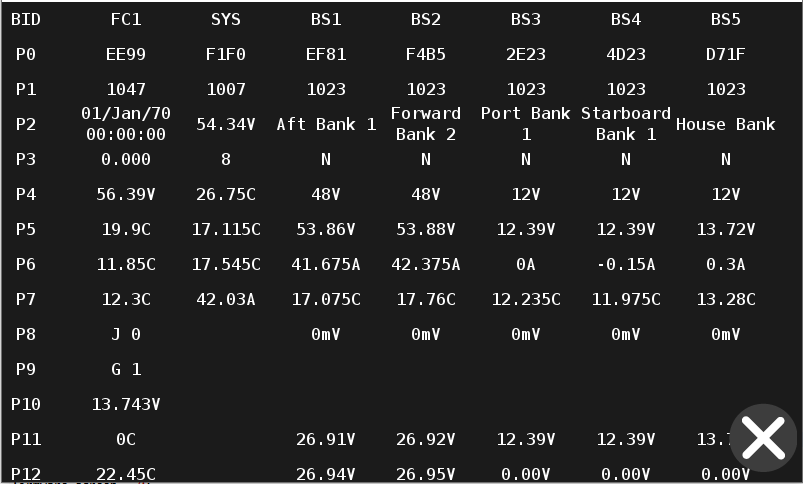
Access the Diagnostic Page via Settings > Advanced > Integrel Diagnostics. The Diagnostic Page is divided into columns. Each column displays information (parameters) related to individual Integrel system components such as the Integrel Controller, Bank Sensor, or Smart Switch. Parameters are numbered sequentially and provide varying information depending on the component. The following tables provide a decoder for each parameter.
¶ v3.x Firmware (Standard)
If you are running verrsion 2.x software see our legacy diagnostic tables below
¶ Controller Parameters
| Parameter | Name | Description |
|---|---|---|
| P3 | Target Voltage | The target voltage the system will charge to (Bulk, Float, or BMS-requested) |
| P4 | Ambient Temperature | Temperature measured by the ambient temperature sensor |
| P5 | OEG Temperature | Temperature measured by the OEG internal temperature sensor |
| P6 | Engine Temperature | Temperature from engine sensor or J1939 data (if connected) |
| P7 | 12V Supply Voltage | Controller 12V power supply voltage. System may not operate correctly if below 12V |
| P8 | Available Power | Amount of available power for generation (watts) |
| P9 | Controller Temp | Temperature of the Controller rectifying diode |
| P10 | Field Coil Voltage | Controller field coil driver voltage (57.6V nominal) |
| P11 | Field Coil Current | Controller field coil driver current |
| P12 | Power Inhibit Flag | Reason why OEG is not charging (see decoder below) |
| P13 | Last Stop Charge Reason | Reason why OEG stopped charging last time (see decoder below) |
| P14 | Alert Flags | System alert flags (see decoder below) |
| P15 | Generator Voltage | Voltage read by controller main 48V positive and negative |
| P16 | Generator Current | Charge current of the controller |
| P17 | Argo/J1939 Error Counts | Argo TEC, Argo REC, J1939 TEC, J1939 REC |
| P18 | N2K Error Counts | NMEA Error count on Transmit and Receive |
| P19 | Voltage Sensing Quality | Voltage sense quality on 48V. Below 80% contact support |
| P20 | PCB Temperature | Temperature measured on the controller PCB |
¶ P12: Generation Inhibit Reason
| Code | Reason |
|---|---|
| 1 | Switch is Open |
| 2 | System paused due to Configuration / Debug |
| 3 | Memory integrity check failure |
| 4 | System voltage is too high / too low |
| 5 | Engine is too cold |
| 6 | Generation manually turned off (using Integrel Touchscreen) |
| 7 | Controller has overheated |
| 8 | BMS has instructed the system to stop charging |
| 9 | Maximum engine RPM exceeded |
| 10 | Gear Change |
¶ P13: Last PWM Zero Reason
| Code | Reason |
|---|---|
| 1 | Low RPM |
| 2 | Over voltage |
| 3 | OEG exceeded emergency temperature |
| 4 | OEG over current |
| 5 | OEG exceeded available engine power |
| 6 | PWM Negative (not used) |
| 7 | PWM RPM Delta (not used) |
| 8 | Low voltage detected by Controller |
| 9 | System detected a gear change event |
| 10 | Engine too cold to begin charging |
| 11 | MG cutoff (not used) |
| 12 | Stopped to receive new parameter settings |
| 13 | Maximum engine RPM exceeded |
¶ P14: Alert Status
| Code | Reason |
|---|---|
| 1 | ARGO: No CAN data received |
| 2 | J1939: No CAN data received |
| 3 | NMEA2K: No CAN data received |
| 4 | J1939 Comms Lost |
| 5 | Slave Controller Flag |
| 6 | BMS CAN data recognised |
| 7 | Limp mode active |
| 8 | Not charging due to SoC limit |
¶ Smart Switch Parameters
| Parameter | Name | Description |
|---|---|---|
| P3 | Switch Voltage 48V | Battery voltage measured by the Switch |
| P4 | Max Bank Current | Total combined current read by all 48V bank sensors |
| P5 | Ambient Temperature | Temperature from external short sensor |
| P6 | Last Disconnect Reason | Reason the Switch contactor last opened (see decoder below) |
| P7 | Battery Temperature 1 | Temperature from external long sensor (battery terminal) |
| P8 | Battery Temperature 2 | Internal sensor reading |
| P9 | IO Signal 1 (ATD) | Voltage for Allow to Discharge. Below 10V = not allowed |
| P10 | IO Signal 1 (ATC) | Voltage for Allow to Charge. Below 10V = not allowed |
¶ P6: Last Disconnect Reason (Smart Switch)
| Code | Description | Code | Description |
|---|---|---|---|
| 1 | SIGNAL1_NO_DISCHARGE (Green/Purple IO wire) | 9 | Panic Disconnect |
| 2 | SIGNAL2_NO_CHARGE (Green/Purple IO wire) | 10 | High Temperature Disconnect (Battery sensor) |
| 3 | High Voltage (Switch V Tap) | 11 | Low Temperature Disconnect (Battery sensor) |
| 4 | Low Voltage (Switch V Tap) | 12 | Missing temperature |
| 5 | High Current (total from all 48V bank sensors) | 13 | Switch Stuck on: contactor fused or switch held closed |
| 6 | High Temperature Disconnect (Ambient sensor) | 14 | Switch Stuck off: locked off or solenoid failure |
| 7 | Low Temperature Disconnect (Ambient sensor) | 15 | Battery missing |
| 8 | User Disconnect | 22 | Device Class Corrupt |
¶ Bank Sensor Parameters
| Parameter | Name | Description |
|---|---|---|
| P3 | Bank Name | Human-friendly name for the Bank Sensor |
| P4 | Mode (N/B/F/E) | Charging mode: N – Not charging, B – Bulk, F – Float, E – Equalising |
| P5 | Bank Sensor Type | Battery type being monitored (12V/24V/48V) |
| P6 | Battery Voltage | Measured voltage of the battery bank |
| P7 | Battery Current | Measured current of the battery bank |
| P8 | Battery Temperature | Measured temperature of the battery bank terminal |
| P9 | Voltage Offset | Offset between system voltage (Controller) and bank sensor voltage reading |
| P10 | Bank Actual SoC | State of charge reading |
| P11 | Bank Reference SoC | Reference state of charge |
| P12-P15 | Block Voltage 1-4 | Measured voltage of Tap 1, 2, 3, 4 |
¶ Legacy v2.x Firmware
Expand to view Legacy v2.x Diagnostic Tables
These tables apply to systems running firmware v2.x (typically with older Parker PHD displays). Parameter numbering differs from v3.x systems.
¶ Diagnostic Page Parameter Summary
| Parameter | Controller (FC) | System/Switch (SYS) | Bank Sensor (BS) |
|---|---|---|---|
| P0 | EUID | EUID | EUID |
| P1 | Firmware version | Firmware version | Firmware version |
| P2 | Manufacture Date | Manufacture Date | Manufacture Date |
| P3 | Hardware Revision | Hardware Revision | Hardware Revision |
| P4 | Target Voltage | Switch Voltage 48V | Bank name |
| P5 | Ambient Temperature | Last disconnect reason | Charge Mode (N/B/F/E) |
| P6 | OEG Temperature | Ambient Temperature | Bank Sensor Type (12V/24V/48V) |
| P7 | Engine Temperature | Battery Temperature 1 | Battery Voltage |
| P8 | J1939 Interface Status | Battery Temperature 2 | Battery Current |
| P9 | Engine Gear Status | Total system current | Battery Temperature |
| P10 | 12V supply voltage | Allow updates config | Voltage Offset |
| P11 | NMEA fault flags | Screen Faults | Bank Actual SoC |
| P12 | Diode Temperature | Buzzer Enabled | Bank Reference SoC |
| P13 | Field Coil Voltage | DCM Current Limit | Block Voltage 1 |
| P14 | Field Coil Current | — | Block Voltage 2 |
| P15 | Generation Inhibit Reason | — | Block Voltage 3 |
| P16 | Last Generation Inhibit Reason | — | Block Voltage 4 |
| P17 | Last Zero PWM Reason | — | — |
| P18 | Alert Status | — | — |
| P19 | 48V System Voltage | — | — |
| P20 | 48V System Current | — | — |
| P21 | CAN Error Statistics 1: Argo/J1939 | — | — |
| P22 | CAN Error Statistics 2: N2K | — | — |
| P23 | System Voltage Sample Quality | — | — |
¶ Controller Parameters
| Parameter | Name | Description |
|---|---|---|
| P0 | EUID | The four digit ARGO CAN bus ID of the Controller (e.g. D14E) |
| P1 | Firmware version | The firmware version running on the Controller |
| P2 | Manufacture Date | Manufacturing date of the Controller |
| P3 | Hardware Revision | Hardware revision of the circuit board |
| P4 | Target Voltage | The target voltage the system will charge to. May be Bulk, Float, or BMS requested |
| P5 | Ambient Temperature | Temperature measured by the ambient temperature sensor |
| P6 | OEG Temperature | Temperature measured by the OEG internal temperature sensor |
| P7 | Engine Temperature | Temperature from engine sensor or J1939 data (if connected) |
| P8 | J1939 Interface Status | JX: J1939 is (1) / is not (0) being received. EX: Engine RPM from J1939. GX: OEG Generator RPM (estimated) |
| P9 | Engine Gear Status | G0: Engine is out of gear. G1: Engine is in gear |
| P10 | Supply voltage | Controller 12V (nominal) power supply voltage. System may malfunction below 12V |
| P11 | NMEA Faults | NMEA fault indicator (see NMEA Faults decoder) |
| P12 | Diode Temperature | Temperature of the Controller rectifying diode |
| P13 | Field Coil Voltage | Controller field coil driver voltage (57.6V nominal) |
| P14 | Field Coil Current | Controller field coil driver current |
| P15 | Generation Inhibit Reason | Current reason OEG is not charging (see P15/P16 decoder) |
| P16 | Last Generation Inhibit Reason | Reason OEG stopped charging last time (see P15/P16 decoder) |
| P17 | Last Zero PWM Reason | Reason PWM output is zero (see P17 decoder) |
| P18 | Alert Status | CAN bus alert status (see P18 decoder) |
| P19 | 48V System Voltage | System voltage at the 48V output of the rectifying diode |
| P20 | 48V System Current | System current measured by the hall effect sensor |
| P21 | CAN Error Statistics 1 | ARGO TEC/REC error count, J1939 TEC/REC error count |
| P22 | CAN Error Statistics 2 | NMEA2000 TEC/REC error count |
¶ NMEA Faults (P11)
| Code | Fault |
|---|---|
| 1 | BMS Inconclusive (more than one BMS found) |
| 2 | NMEA address conflict (badly behaving device on N2K) |
| 3 | BMS missing (BMS not found) |
| 4 | Masterbus battery configuration is incorrect |
| 5 | Internal software string error (internal use) |
| 6 | NMEA device list is full (network has too many devices) |
| 7 | Reserved |
| 8 | Reserved |
¶ Generation Inhibit Reason (P15/P16)
| Code | Reason |
|---|---|
| 1 | Switch is Open |
| 2 | System paused due to Configuration / Debug |
| 3 | Memory integrity check failure |
| 4 | System voltage is too high / too low |
| 5 | Engine is too cold |
| 6 | Generation manually turned off (using Integrel Touchscreen) |
| 7 | The Controller has overheated |
| 8 | The BMS has instructed the system to stop charging |
| 9 | Maximum engine RPM exceeded |
¶ Last PWM Zero Reason (P17)
| Code | Reason |
|---|---|
| 1 | Low RPM |
| 2 | Over voltage |
| 3 | OEG exceeded emergency temperature |
| 4 | OEG over current |
| 5 | OEG exceeded available engine power |
| 6 | PWM Negative (not used) |
| 7 | PWM RPM Delta (not used) |
| 8 | Low voltage detected by Controller |
| 9 | The system detected a gear change event |
| 10 | Engine too cold to begin charging |
| 11 | MG cutoff (not used) |
| 12 | Stopped to receive new parameter settings |
| 13 | Maximum engine RPM exceeded |
¶ Alert Status (P18)
| Code | Reason |
|---|---|
| 1 | ARGO: No CAN data received |
| 2 | J1939: No CAN data received |
| 3 | NMEA2K: No CAN data received |
| 4 | J1939 Comms Lost |
| 5 | Slave Controller Flag |
| 6 | BMS CAN data recognised |
| 7 | Limp mode active |
| 8 | Not charging due to SoC limit |
¶ Smart Switch Parameters
| Parameter | Name | Description |
|---|---|---|
| P0 | EUID | The four digit ARGO CAN bus ID (e.g. D14E) |
| P1 | Firmware version | The firmware version running on the Switch |
| P2 | Manufacture Date | Manufacture date of the Switch hardware |
| P3 | Hardware Revision | Hardware revision of the circuit board |
| P4 | Switch Voltage | Battery voltage measured by the Switch (48V nominal) |
| P5 | Last disconnect reason | Reason the Switch contactor last opened (see P5 decoder) |
| P6 | Internal Temperature | Temperature measured by the ambient temperature sensor |
| P7 | Battery Temperature | Temperature measured by the battery terminal sensor |
| P8 | Ambient Temperature | Temperature measured by the ambient air sensor |
| P9 | Total system current | Total current flowing into/out of the battery bank |
| P10 | Allow Updates Config | — |
| P11 | Screen Faults | — |
| P12 | Buzzer Enabled | — |
| P13 | DCM Current Limit | — |
¶ Last Disconnect Reason (P5)
| Code | Description |
|---|---|
| 1 | SIGNAL1_NO_DISCHARGE (Green/Purple IO wire) |
| 2 | SIGNAL2_NO_CHARGE (Green/Purple IO wire) |
| 3 | High Voltage (Switch V Tap) |
| 4 | Low Voltage (Switch V Tap) |
| 5 | High Current (total current measured by all 48V bank sensors) |
| 6 | High Temperature Disconnect (Ambient sensor) |
| 7 | Low Temperature Disconnect (Ambient sensor) |
| 8 | User Disconnect |
| 9 | Panic Disconnect |
| 10 | High Temperature Disconnect (Battery sensor) |
| 11 | Low Temperature Disconnect (Battery sensor) |
| 12 | Missing temperature |
| 13 | Switch Stuck on: contactor fused or switch held closed |
| 14 | Switch Stuck off: locked in the off position or solenoid failure |
| 15 | Battery missing |
| 16 | BMS Error (Torqeedo) |
| 17 | BMS Block missing (Torqeedo) |
| 18 | BMS enumeration failed (Torqeedo) |
| 19 | BMS enumeration time out (Torqeedo) |
| 20 | BMS warning (Torqeedo) |
| 21 | BMS Discharge (All BMS systems) |
| 22 | Device Class Corrupt |
| 23–26 | Reserved |
¶ Bank Sensor Parameters
| Parameter | Name | Description |
|---|---|---|
| P0 | EUID | The four digit ARGO CAN bus ID (e.g. D14E) |
| P1 | Firmware version | The firmware version running on the Bank Sensor |
| P2 | Manufacture Date | Manufacturing date of the Bank Sensor hardware |
| P3 | Hardware Revision | Hardware revision of the board |
| P4 | Bank name | Human friendly name for the Bank Sensor |
| P5 | Mode (N/B/F/E) | Charging mode: N – Not charging, B – Charging to Bulk, F – Charging to Float, E – Equalising |
| P6 | Bank Sensor Type | Battery type being monitored (12V/24V/48V) |
| P7 | Battery Voltage | Measured voltage of the battery bank |
| P8 | Battery Current | Measured current of the battery bank |
| P9 | Battery Temperature | Measured temperature of the battery bank terminal |
| P10 | Voltage Offset | Offset between system voltage (Controller) and bank sensor voltage reading |
| P11 | Bank Actual SoC | State of charge reading |
| P12 | Bank Reference SoC | Reference state of charge |
| P13 | Block voltage 1 | Measured voltage of Tap 1 |
| P14 | Block voltage 2 | Measured voltage of Tap 2 |
| P15 | Block voltage 3 | Measured voltage of Tap 3 |
| P16 | Block voltage 4 | Measured voltage of Tap 4 |
¶ BMS Diagnostics
BMS error codes are passed transparently from the BMS.
BMS Status Flags
| Flag | Description |
|---|---|
| 1 | Contactor closed (charge) |
| 2 | Allow to Charge |
| 3 | Allow to Discharge |
| 4 | Is alive |
| 5 | Is charging |
| 6 | Is discharging |
| 7 | Contactor closed (load) |
| 8 | Charged |
BMS Warning Flags
| Flag | Description |
|---|---|
| 1 | Over Voltage |
| 2 | Under Voltage |
| 3 | High charge Current |
| 4 | High Discharge Current |
| 5 | Charging Suspended (By Integrel, due to BMS) |
| 6 | Balancing in progress |
| 7 | DCL enabled (Dynamic Current Limiting, Lithionics only) |
| 8 | Reserved |
¶ Troubleshooting Table
The following table lists potential issues that may occur during installation, testing, and commissioning.
| Issue | Possible Cause | Solution |
|---|---|---|
| Battery page: No battery data | No CAN bus connection to Bank Sensor | Check RJ45 cable connection between battery bank sensor(s) and Integrel Argo CAN bus network |
| Smart Switch not connecting | No CAN bus connection to Smart Switch | Check RJ45 cable connection between Smart Switch and Integrel Argo CAN network |
| Controllers or other devices missing from the touchscreen | Faulty device, cable, port, or network termination | See Isolating a Network Fault |
| Battery page: Battery showing 0V | Battery voltage tap on backwards | Check voltage taps are wired correctly. If backwards, voltages may be incorrect or zeroed out |
| Battery page: kW reading is backwards (negative when charging, positive when discharging) | Bank Sensor is installed backwards | Contact Integrel Support; this is corrected in settings without rewiring |
| PWM at 100% but no power generation | Blown fuse or generator failure | Contact Integrel Support |
| PWM at 99% but low power generation | 12V supply to controller may be low | Check 12V supply voltage of house bank. If monitoring with 12V Bank Sensor, verify it shows >12.0V |
| PWM at 99% but low power generation | OEG phase cable(s) damaged | Check OEG phase cables are connected and not damaged |
| Engine RPM is incorrect | System configuration needs adjustment | Contact Integrel Support |
| RPM not showing on touchscreen | Phase connections | Check phase connections |
| RPM not showing on touchscreen | Loom fault | Check loom is not damaged. Check noise is not coupling into the loom from nearby cables |
| RPM not showing on touchscreen | System in diagnostic mode | Disconnect USB or Bluetooth, cycle system power |
| RPM not showing on touchscreen | Controller board failure | Check J1939 connection (if enabled). Contact Integrel Support otherwise |
| Touchscreen shows "Max voltage exceeded" | Li-ion setting wrong | Check Li-ion settings |
| Battery voltage dropping below cut out voltage | Load device connected between Smart Switch and battery bank | Check switch settings are correct and check wiring configuration. A single 24V nominal Lithium battery should never drop below 20V |
| Engine seems to be overloaded | System configuration needs adjustment | Contact Integrel Support; several settings interact here and we will review them with you |
| Engine seems to be overloaded | In-gear detection failing | For engines <50hp, check in-gear cable/switch is connected and working. Check J1939 in-gear configuration (Yanmar only) |
| Integrel Panel Switch keeps tripping | Faulty switch | Try a higher current rated switch, no more than 10 amps |
| Integrel Panel Switch keeps tripping | Controller fault | Check voltage to Controller and that PWM is wired correctly |
| Message: Battery missing (Smart Switch) | 48V V tap missing | The 48V V tap for the switch is missing |
| Message: Battery missing (Smart Switch) | Internal fault | Contact Integrel Support |
| Controller has 12V but not powering | Internal fault | Contact Integrel Support |
| Generator temperature reads -77°C | Connection is open circuit or temperature sensor is damaged | Check connection between controller and OEG temperature pins. This may also mean a failed sensor |
| Audible noise in the stereo or audio system, or interference with sensitive DC equipment such as watermaker pumps, while the system is generating | Electrical noise from the E-Power system during generation | Fit the E-Power Noise Suppression Kit, one per Controller. Compatible with all controller versions (Legacy, v4 Molex, and v5 M12). See the installation guide on the Manuals page. The noise is present only while the system is generating |
¶ Integrel Argo Network
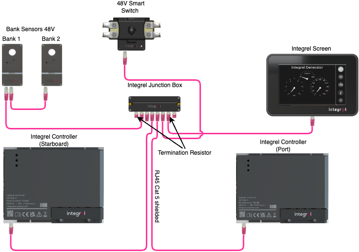
The Integrel Argo network is the CAN bus network that connects the Integrel Controllers, Integrel Touchscreen, Bank Sensors, and Smart Switch through the Integrel Junction Box, using shielded CAT5 cable with RJ45 plugs. It is separate from any NMEA 2000 or Victron VE.Can network on the boat.
¶ Signs of a Network Problem
- Controllers or other devices missing from the Touchscreen
- Touchscreen shows an error reading ID 0001 or FFFF
- The system repeatedly enters limp mode, or devices appear and disappear
¶ Quick Checks
- Termination. The network needs exactly two termination resistors, fitted at the ends of the two longest cable runs. Too few or too many resistors cause the same symptoms as a faulty device.
- Cable type. Argo network cable must be shielded CAT5. Unshielded or damaged cable can cause intermittent errors.
- RJ45 connections. A plug forced into a Junction Box port at an angle can short several pins together. Unplug and reseat any suspect connection straight in.
If these checks do not resolve the issue, isolate the fault with the procedure below.
¶ Isolating a Network Fault
One faulty device, cable, or port on the Integrel Argo Network can disrupt communication across the whole system. To find it, reduce the network to one Touchscreen and one Controller, confirm that setup works, then reconnect everything else one item at a time. The last item connected before communication fails is the fault.
Use this procedure when:
- Controllers or other devices do not appear on the Touchscreen
- Devices appear and disappear, or the system repeatedly enters limp mode
- The problem remains after the network cables have been checked or replaced
WARNING: Integrel RJ45 wiring is not standard Ethernet. Never connect the Integrel network to a computer, router, or any other boat data network. Doing so can damage the Integrel Controller.
NOTE: This procedure uses only the RJ45 network plugs. Do not remove the Controller cover or disconnect any 48V cables.
¶ What You Need
- A short CAT5 cable with RJ45 plugs
- One Integrel termination resistor
¶ Before You Start
- Note the LED state on each Controller. See Controller LED Status.
- If the Touchscreen is on, photograph the top and bottom of the diagnostic page (Settings > Advanced > Integrel Diagnostics).
- Label each network cable at the junction box so every cable returns to its original port.
¶ Step 1: Test One Controller With the Touchscreen
- Power off the Integrel system at the switch panel.
- Unplug every network cable from the junction box.
- Connect the Touchscreen directly to one Controller network port with the short CAT5 cable.
- Fit the termination resistor in a spare RJ45 port on the Touchscreen.
- Power on the Controller at the switch panel.
- Check the Touchscreen.
| Result | Meaning | Next Step |
|---|---|---|
| Touchscreen powers on and shows Controller data | Controller and Touchscreen are working. The fault is elsewhere on the network | Go to Step 2 |
| Touchscreen stays blank or shows no Controller data | The fault is in the Controller, the Touchscreen, or the test cable | Try a different test cable. If the result is the same, contact Integrel Support |
¶ Step 2: Test the Second Controller
On a two engine system, repeat Step 1 with the second Controller. Both Controllers must pass before you continue.
¶ Step 3: Rebuild the Network One Item at a Time
NOTE: A short network operates with one termination resistor. The complete network needs two. See Check Network Termination.
- Reconnect the Touchscreen and one working Controller to the junction box with their installed cables.
- Refit the termination resistors in their installed positions.
- Check that the Touchscreen shows Controller data.
- Reconnect one more device or cable.
- Check the Touchscreen. If every connected device shows data, repeat step 4 with the next item.
- Stop when communication fails. The item you connected last is the fault.
| Last Item Connected | Likely Cause | How to Confirm |
|---|---|---|
| A device (Controller, Bank Sensor, or Smart Switch) | Faulty device | Connect the device to a different junction box port with a known good cable. If the fault follows the device, contact Integrel Support |
| A cable | Damaged or corroded cable or RJ45 plug | Replace the cable, or test it with a network cable tester |
| A junction box port | Faulty port | Move the cable to a spare port |
¶ Check Network Termination
Incorrect termination causes the same symptoms as a faulty device. Once the network is rebuilt, confirm it matches the termination rule under Quick Checks.
¶ After Communication Is Restored
Other faults can stay hidden while the network is down. Once every device shows on the Touchscreen, photograph the top and bottom of the diagnostic page again and send the photos to Integrel Support.
NOTE: Restore network communication before considering a hard reset, and contact Integrel Support before performing one.
¶ System Resets
Occasionally a system reset is required to clear errors or restore normal operation.
| Symptom | Reset Type | Check After Reset |
|---|---|---|
| Error on screen that will not clear | Soft Reset | — |
| Start-up self-check warning | Soft Reset | Check 12V supply can deliver 15 amps per controller |
| Error on screen reading ID 0001 or FFFF | Full System Reset | Check network termination and that network uses shielded cables |
| Controller has frozen, fans running continuously | Hard Reset | Check 12V supply can deliver 15 amps per controller. A power drop may cause this issue (may happen during software update if power drops) |
Note: Report any of the above issues to support@integrelsolutions.com
¶ Soft Reset
Power off both controllers, leave for 10 seconds, then repower.
¶ Full System Reset
- Power off the Controllers.
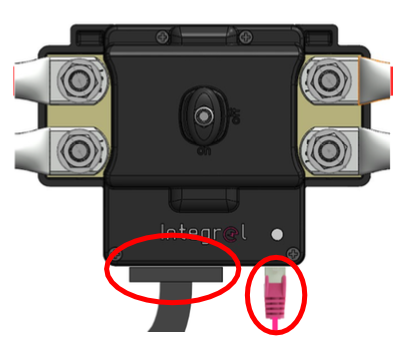
- Disconnect the Integrel Smart Switch (both network and data cables).
- Wait 10 seconds.
- Reconnect the Smart Switch.
- Power on both controllers.
¶ Hard Reset
Warning: A hard reset is rare but may be required if the controller has frozen. Contact Integrel Support before performing a hard reset.
¶ Contact Support
If troubleshooting steps do not resolve your issue:
-
Gather Information:
- System serial number
- Software version (Settings > About)
- Description of the issue
- Photos or screenshots of the Integrel Diagnostic Page (Settings > Advanced > Diagnostics)
-
Submit a Request: